Introduction
In part one of this series, I described how to write an interpreter for raw GPS NMEA data. Part two described how to monitor and enforce GPS precision data to develop commercial-quality software. The articles included source code in C# and VB.NET which harnessed the power of GPS satellites to determine the current location, synchronize the computer clock to atomic time, and point to a satellite on a cloudy day. Yet, even with all of this code, most developers still need a way to display GPS information along with other geographic features. With the help of my colleague Phil Smith, a lead developer of our "GIS.NET" mapping component and the "Geodesy.NET" coordinate and projection library, this article will teach you how to generate your own maps.
The Rule of Threes
In order to understand the technology behind mapping, it's necessary to have a solid understanding of three coordinate systems: geographic, projected, and pixel. Each system serves an important role when displaying a map, and transformations from one system to another are essential. Developers typically start with a geographic coordinate (expressed as latitude and longitude). Then, it is transformed from Earth's eblate spheriod (roughly spherical) shape to a plane, resulting in a projected coordinate: a truly flat, two-dimensional coordinate. A projected coordinate is an easting/northing pair, describing a distance East of a "central meridian" (a line of longitude) and a distance North of a "central parallel" (a line of latitude). The method which transforms a geographic coordinate to and from a projected easting/northing coordinate is called a projection. Finally, projected coordinates are translated and scaled so that they align to a specific place on-screen, resulting in pixel coordinates. Pixel coordinates are the same coordinates that you've already used to align controls on a Form.

Figure 1.1: Geographic coordinates are converted from 3D to 2D using a map projection. Then, a viewport scales and translates a portion of the map to display Florida.
Let's take a closer look at each of the three coordinate systems and how to convert between them to produce a map.
The Earth is Better Flat
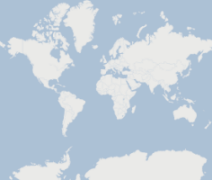
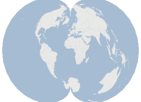
In parts one two of this article, we discussed how GPS devices report your location as a latitude and longitude. These pairs are often referred to as "geographic coordinates." The problem with geographic coordinates, however, is that they represent coordinates on Earth's surface, which is a spheroid (spherical) shape. Since our computer monitors are flat, we need a way to "unfold" the Earth into a perfectly flat shape before we try to display it. This technique is known as projection and it is essential for displaying maps. There are over a hundred map projections in use around the world today, and each projection serves a specific purpose. For example, the Mercator projection is widely used by boats and ships because it produces a map in which lines of constant bearing are a straight line, which greatly simplifies navigation. However, a side-effect of this projection is that it distorts the size of everything as you get closer to the North or South Poles, making this projection unsuitable for other purposes.


Figure 1.2: Countries of the world are displayed using two projections, Mercator and Polyconic, to demonstrate how projections can produce widely-differing views of the same data.
As you can see, map projections can make the same geographic features appear in completely different sizes and shapes, but each is perfectly valid. In fact, some projections such as the "Orthographic" projection are flat put produce the illusion of a 3D image on a flat monitor. This projection is a contemporary example which is widely used by many 3D applications, including modern 3D game engines. Regardless of the shape and size, projected coordinates flatten 3D coordinates, and this greatly simplifies the task of mapping.
Here Comes the Science
The mathematics behind map projections can be somewhat intimidating. For example, the "Van der Grinten" projection uses the following formula (where A, G, and P are mapping parameters):


For this article, we'll be writing the code for a much simpler projection known as "Equidistant Cylindrical" or "Plate Carée," which, because of its simplicity and speed, is the default projection used by our GIS.NET 3.0 component, which includes a library of twenty-five other projections:

The formulas for map projection are easier to work with when geographic coordinates are expressed as radians. Radians are straightforward to calculate, and can be applied to either a latitude or longitude:
// ninety degrees
double degrees = 90.0;
// Convert to radians
double radians = degrees * (Math.Pi / 180.0);
// Convert radians back to degrees
degrees = radians / (Math.PI / 180.0);
All map projection source code is divided into two methods. The first method, referred to as a forward projection, will convert a geographic coordinate into a projected coordinate. The second method is exactly the opposite, converting a projected coordinate back into a geographic coordinate. This is referred to as a reverse projection or de-projection. Here's how the two methods look for our example Plate Carée projection:
using System.Drawing;
public class PlateCaree
{
public PointF Project(PointF geographicCoordinate)
{
// First, convert the geographic coordinate to radians
double radianX = geographicCoordinate.X * (Math.PI / 180);
double radianY = geographicCoordinate.Y * (Math.PI / 180);
// Make a new Point object
PointF result = new PointF();
// Calculate the projected X coordinate
result.X = (float)(radianX * Math.Cos(0));
// Calculate the projected Y coordinate
result.Y = (float)radianY;
// Return the result
return result;
}
public PointF Deproject(PointF projectedCoordinate)
{
// Make a new point to store the result
PointF result = new PointF();
// Calculate the geographic X coordinate (longitude)
result.X = (float)(projectedCoordinate.X / Math.Cos(0) / (Math.PI / 180.0));
// Calculate the geographic Y coordinate (latitude)
result.Y = (float)(projectedCoordinate.Y / (Math.PI / 180.0));
return result;
}
}
With this class, we can now produce projected coordinates for any location on Earth:
// Define a geographic coordinate, in this case a GPS location
PointF myLocation = new PointF();
myLocation.Y = 39.0; // 39 North
myLocation.X = -105.0; // 105 West
// Now use our projection class to flatten this coordinate
PlateCaree projection = new PlateCaree();
PointF myProjectedLocation = projection.Project(myLocation);
myLocation = projection.Deproject(myProjectedLocation);
... this process is then repeated for each geographic coordinate until all data can be represented in projected coordinates. Once this has been done, only one step remains to convert these coordinates into pixel coordinates which can be painted on the screen.
Paint the Planet
If we were creating a map to display on a wall, our task would be easy because we could paint all of the data once and be done with it. However, mapping software should let users pan and zoom a map so that they can explore any part of it in greater detail. To do this, we must imagine a rectangle (which we refer to as a "viewport" in GIS.NET 3.0) which represents the portion of the map we actually want to see. Once this is known, math is applied a third time to convert projected coordinates into pixel coordinates. In other words, we must make the upper-left of our viewport match up to (0,0) in our Form.

Figure 1.4: A viewport is used to see a portion of all projected coordinates. In this case, a viewport displays the continent of Africa.
.NET developers are already familiar with pixel coordinates. These are the same coordinates which you've used to place controls onto a Form, so there's nothing new to explain here. But, we need a way to convert projected coordinates into pixel coordinates. To do this, projected coordinates must be scaled and translated to make the viewport align with the pixel size of the Form. Translation is performed by applying the negative value of the X coordinate, then the Y coordinates of the upper-left corner of the viewport. Horizontal scale is calculated by dividing the pixel width of the area to paint by the projected width of the viewport, and similarly to calculate vertical scale.
Fortunately, on desktops, we can make use of the Matrix class to do all of the heavy lifting for this task. Matrix objects can rotate, translate and scale an array of coordinates in the form of a PointF array. The resulting code will look something like this:
// Use a matrix for translation and scaling
Matrix transform = new Matrix();
// First, translate all projected points so that they match up with pixel 0,0
transform.Translate(-viewport.X, viewport.Y, MatrixOrder.Append);
// Next, scale all points so that the viewport fits inside the form.
transform.Scale(this.Width / viewport.Width,
this.Height / -viewport.Height, MatrixOrder.Append);
You may have noticed how, for vertical scale, a negative sign is used. This is because projected coordinate systems have a Y-axis which is the opposite of pixel coordinate systems. In other words, greater Y values travel up in projected coordinates, whereas greater Y values in pixel coordinates travel down. A negative sign here prevents the image from being displayed upside-down.
Since we're using GDI+ for this example, all painting is done using a Graphics class, typically during an OnPaint method. Thankfully, we can apply our transformation and scale easily by assigning the Transform property of the Graphics object to our Matrix. With this in place, we can now call paint methods such as DrawLine using projected coordinates! As a result, painting objects becomes rather trivial:
protected override void OnPaint(PaintEventArgs e)
{
// Apply this transform to all graphics operations
e.Graphics.Transform = transform;
// Now draw nebraska using a green interior and black outline
e.Graphics.FillPolygon(Brushes.Green, projectedCoordinates);
e.Graphics.DrawPolygon(Pens.Black, projectedCoordinates);
}
Have a Good Aspect
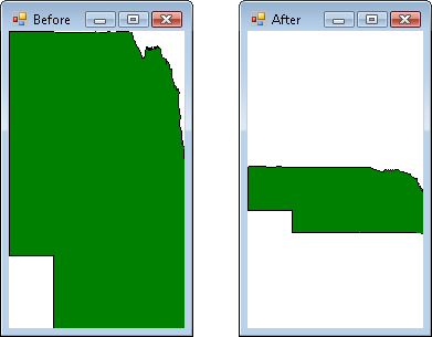
In this article, we're dealing with two rectangles: the "viewport," a projected area to be painted, and the Form itself, where everything will be displayed. If the shape of the viewport differs greatly from the shape of the Form, however, distortion can occur (see the "Before" picture below). To fix this problem, we must make the shape of the viewport match the shape of the Form. This is done by adjusting the "aspect ratio" of the viewport.

Figure 1.5: The state of Nebraska is drawn with no correction (left), then with aspect ratio correction (right) to preserve its shape.
Aspect ratio is calculated by dividing the width of a rectangle by its height. For example, if the width of a rectangle were ten pixels, and its height were twenty pixels, then the aspect ratio would be 0.5. To adjust the aspect ratio of the viewport, its aspect ratio is compared to the aspect ratio of the rectangular Form itself. If the viewport's aspect ratio is greater than the Form's, the viewport's height is increased. Otherwise, the viewport's width is increased. The resulting code looks like this:
// Calculate the aspect ratio of the Form
float pixelAspectRatio = (float)this.Width / this.Height;
// Calculate the aspect ratio of the viewport
float projectedAspectRatio = viewport.Width / viewport.Height;
// Make a copy of the viewport that we can change
RectangleF adjustedViewport = viewport;
// Is the Form's aspect ratio larger than the viewport's ratio?
if (pixelAspectRatio > projectedAspectRatio)
{
// Yes. Increase the width of the viewport
adjustedViewport.Inflate((pixelAspectRatio * adjustedViewport.Height - adjustedViewport.Width)/ 2,0);
}
// Is the viewport's aspect ratio larger than the form's ratio?
else if (pixelAspectRatio < projectedAspectRatio)
{
// Yes. Increase the height of the viewport
adjustedViewport.Inflate(0, (adjustedViewport.Width / pixelAspectRatio - adjustedViewport.Height) / 2);
}
… with the aspect ratio adjusted, all geographic objects painted will now preserve their shape even as the Form's shape changes.
Navigating a Map
Now that we have the ability to paint a portion of a map, the final step in this example is to implement some form of navigation. Panning a map means shifting the viewport without changing its size. Zooming, however, is somewhat counter-intuitive: to zoom a map in, you must make the projected viewport smaller. A smaller viewport means a greater scale factor is applied.
If we're using the PointF class to represent projected coordinates, we can use the RectangleF class to represent the projected viewport. Zooming becomes a matter of calling the Inflate method to either shrink or grow the projected viewport to zoom in or out, respectively. Another important thing to mention here is the concept of "zooming by percentage." Zooming should always be done using a percentage of the current viewport. Otherwise, zooming will appear to have an exaggerated effect the more you zoom in, and closer to no effect as you zoom out:
public void ZoomIn()
{
// First, get the width of the viewport, then calculate 10% of it
float zoomWidthAmount = -viewport.Width * 0.10f;
float zoomHeightAmount = -viewport.Height * 0.10f;
// Next, apply the amounts to shrink (yes, shrink) the viewport to zoom in
viewport.Inflate(zoomWidthAmount, zoomHeightAmount);
// And repaint
Invalidate();
}
public void ZoomOut()
{
// First, get the width of the viewport, then calculate 10% of it
float zoomWidthAmount = viewport.Width * 0.10f;
float zoomHeightAmount = viewport.Height * 0.10f;
// Next, apply the amounts to shrink (yes, shrink) the viewport to zoom in
viewport.Inflate(zoomWidthAmount, zoomHeightAmount);
// And repaint
Invalidate();
}
Developers may recognize how easily these methods can be plugged into the MouseWheel event of a Form. Panning methods are just as straightforward, but involve use of the Offset method:
public void PanUp()
{
// First, get the height of the viewport, then calculate 10% of it
float zoomHeightAmount = -viewport.Height * 0.10f;
// Shift the viewport by this amount
viewport.Offset(0.0f, zoomHeightAmount);
}
public void PanDown()
{
// First, get the height of the viewport, then calculate 10% of it
float zoomHeightAmount = viewport.Height * 0.10f;
// Shift the viewport by this amount
viewport.Offset(0.0f, zoomHeightAmount);
}
... again, you may have already recognized how to plug these methods into the KeyDown event. With these methods implemented, you can now explore your map at any zoom level. If you are familiar with parts one and two of this article, you are well on your way to developing a commercial application which can plot your GPS location, along with all kinds of geographic features. Whether your intent is to draw points, lines or polygons, the approach is the same.
Play It Backwards
At this point, we've successfully drawn a map and provided a way to pan and zoom. But it would be helpful to be able to see where the mouse is pointing, but in terms of geographic or projected coordinates, not pixel coordinates. So, we'll add some code into the MouseMove event of the Form which will show the mouse's location in all three coordinate systems.
Conversion starts with pixel coordinates, which are then converted to projected coordinates using the inverse of the Matrix we set up earlier in this article. Finally, the Deproject method of our projection is used to convert the projected coordinate back into its geographic equivalent. The code will look like this:
protected override void OnMouseMove(MouseEventArgs e)
{
/* When the mouse is moved over the map, show the coordinate the mouse
* is hovering over, in all three coordinate systems: pixel, projected,
* and geographic.
*/
/* We use a Matrix to convert from projected coordinates to pixel
* coordinates. The *inverse* of this matrix is used to convert pixels
* back into projected coordinates.
*/
// First, make a copy of the current transform
Matrix reverseTransform = transform.Clone();
// Next, invert the transform
reverseTransform.Invert();
// We can now use this to calculate a projected coordinate.
Point[] projectedCoordinate = new Point[] { e.Location };
reverseTransform.TransformPoints(projectedCoordinate);
/* "Points" now contains projected coordinates. Use our projection to
* convert this into geographic (latitude/longitude) coordinates.
*/
PointF geographicCoordinate = plateCaree.Deproject(projectedCoordinate[0]);
// Finally, display all three coordinates: pixel, projected, geographic
Console.WriteLine("Pixel: " + e.Location.ToString());
Console.WriteLine("Projected: " + projectedCoordinate[0].ToString();
Console.WriteLine("Geographic: " + geographicCoordinate.ToString();
}
… with this code, you can now freely convert between all three coordinate systems, in both directions.
Conclusion
The task of displaying geographic data on-screen involves conversion of the data to two other coordinate systems. Map projections are used to flatten 3D coordinates into 2D coordinates, and then matrix math is used to actually paint geographic data in a meaningful way. Panning and zooming a map involves changing the location and size of the viewport, and navigation is typically tied into keyboard and mouse events. The aspect ratio of the viewport is adjusted to match the aspect ratio of the Form to prevent distortion. Finally, an inverse of the Matrix is used to convert coordinates from pixel to projected, and the Deproject method of the projection converts the projected coordinate back into its geographic equivalent.
There are many topics which we have yet to cover in order to develop a commercial-quality mapping application. Topics such as geographic data sources, spatial indexing, vector normalization, and paint optimization could easily take up another several articles. Many commercial components for .NET exist which address these topics. However, this article can at least help you to gain a solid understanding of how to display geographic data in your own .NET applications.