This article has been excerpted from book "Graphics Programming with GDI+".
The Graphics class provides methods to clip regions. Using these methods, an application can restrict where graphics objects are drawn. One major use of clipping region is to repaint only part of a control. In some cases painting an entire form is costly in terms of time and memory resources. Clipping plays a vital role by painting only the desired area. The Graphics class provides the SetClip, ResetClip, IntersectClip, ExcludeClip and TranslateClip methods to use in clipping operations.
ExcludeClip excludes the area specified by an argument of type Rectangle or a Region and updates the clipping region. Listing 6.11 fills a rectangle, excluding one small rectangle and a region.
LISTING 6.11: Using ExcludeClip to clip regions
//Create a Graphics object
Graphics g = this.CreateGraphics();
g.Clear(this.BackColor);
//Create rectangles
Rectangle rect1 = new Rectangle(20, 20, 60, 80);
Rectangle rect2 = new Rectangle(100, 100, 30, 40);
//Create a region
Region rgn1 = new Region(rect2);
//Exclude clip
g.ExcludeClip(rect1);
g.ExcludeClip(rgn1);
//Fill rectangle
g.FillRectangle(Brushes.Red, 0, 0, 200, 200);
//Dispose of object
g.Dispose();
Figure 6.11 shows output from Listing 6.11. The small rectangle and small region are not updated.
SetClip sets the clipping region of a Graphics object. This method has many overloaded forms and takes parameters of type Rectangle, RectangleF, Region, GraphicsPath, and Graphics with or without the CombineMode enumeration. The CombineMode enumeration defines how different clipping regions can be combined (see Table 6.2).
The ResetClip method resets the clipping region to infinity. Listing 6.12 uses the SetClip, ResetClip, and IntersectClip methods.
Listing 6.12: Using the SetClip, ResetClip, and IntersectClip methods
//Create a Graphics object
Graphics g = this.CreateGraphics();
g.Clear(this.BackColor);
//Create rectangles and regions
Rectangle rect1 = new Rectangle(20, 20, 200, 200);
Rectangle rect2 = new Rectangle(100, 100, 200, 200);
Region rgn1 = new Region(rect1);
Region rgn2 = new Region(rect2);
//Call SetClip
g.SetClip(rgn1, CombineMode.Exclude);
//Call IntersectClip
g.IntersectClip(rgn2);
//Fill rectangle
g.FillRectangle(Brushes.Red, 0, 0, 300, 300);
//Call ResetClip
g.ResetClip();
//Draw rectangles
g.DrawRectangle(Pens.Green, rect1);
g.DrawRectangle(Pens.Yellow, rect2);
//Dispose of objects
g.Dispose();
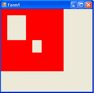
FIGURE 6.11: ExcludeClip Output
TABLE 6.2: CombineMode members
|
Member |
Description |
|
Complement |
The existing region is replaced by the result of the existing region being removed from the new region. |
|
Exclude |
The existing region is replaced by the result of the new region being removed from the existing region. |
|
Intersect |
Two clipping regions are combined and the result is their intersection. |
|
Replace |
One clipping region replaces the other. |
|
Union |
Two clipping regions are combined, and the result is their union. |
|
Xor |
Two clipping regions are combined and the result is their union minus their intersection. |
Note: The CombineMode enumeration is defined in the System.Drawing.Drawing2D namespace.
Figure 6.12 shows the output from Listing 6.12.
TranslateClip translates the clipping region as specified. Listing 6.13 uses the TranslateClip method to translate a region to 20 and 30 points.
LISTING 6.13: Using TranslateClip to translate a region
//Create a Graphics object
Graphics g = this.CreateGraphics();
g.Clear(this.BackColor);
//Create a Rectangle
RectangleF rect1 = new RectangleF(20.0f, 20.0f, 200.0f, 200.0f);
//Create a region
Region rgn1 = new Region(rect1);
//Call SetClip
g.SetClip(rgn1, CombineMode.Exclude);
float h = 20.0f;
float w = 30.0f;
//Call Translate Clip with h and w
g.TranslateClip(h, w);
//Fill rectangle
g.FillRectangle(Brushes.Green, 20, 20, 300, 300);
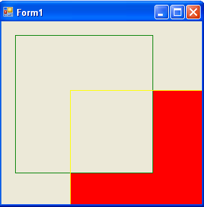
FIGURE 6.12: Using clip mode
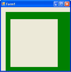
FIGURE 6.13: Using TranslateClip
Figure 6.13 shows the output from Listing 6.13
Clipping Regions Example
Listing 6.14 uses Xor to clip regions
LISTING 6.14: Using the Xor method
Graphics g = e.Graphics;
Pen pen = new Pen(Color.Red, 5);
SolidBrush brush = new SolidBrush(Color.Red);
Rectangle rect1 = new Rectangle(50, 0, 50, 150);
Rectangle rect2 = new Rectangle(0, 50, 150, 50);
Region region = new Region(rect1);
region.Xor(rect2);
g.FillRegion(brush, region);
Figure 6.14 shows the output from Listing 6.14.
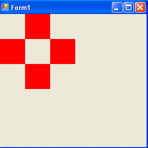
FIGURE 6.14: Result of the Xor method
Now if we replace Xor with Union:
region.Union(rect2);
the new output looks like Figure 6.15.
Now let's replace Union with Exclude:
region.Exclude(rect2);
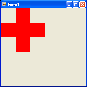
FIGURE 6.15: Result of the Union method
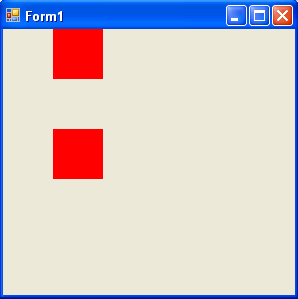
FIGURE 6.16: Result of the Exclude method
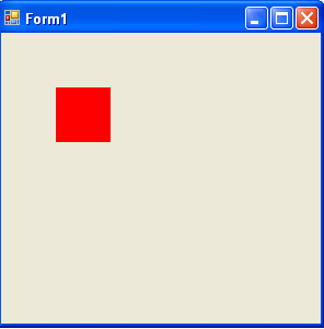
FIGURE 6.17: Result of the Intersect method
The output looks like Figure 6.16.
If we use the Intersect method:
region.Intersect (rect2);
the output looks like Figure 6.17.
Conclusion
Hope the article would have helped you in understanding Regions and Clipping in GDI+. Read other articles on GDI+ on the website.
 |
This book teaches .NET developers how to work with GDI+ as they develop applications that include graphics, or that interact with monitors or printers. It begins by explaining the difference between GDI and GDI+, and covering the basic concepts of graphics programming in Windows. |