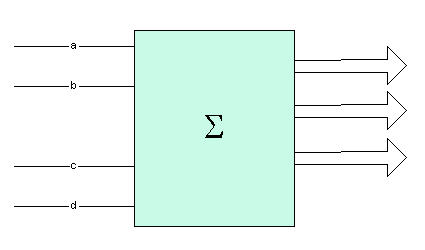
Figure 1 - Adder that adds two 2-bit binary numbers
I just walked into Barnes and Noble the other day and happened upon a very interesting article in the February 2003 issue of Scientific American. The name of the article is Evolving Inventions, by John R. Koza, Martin A. Keane and Matthew J. Streeter. The premise of the article is that Genetic Algorithms can pretty much be used to invent electronic circuits. The article then goes to explain that GA (Genetic Algorithms) have been used by various programmers to come up with 15 previous patented inventions + (and here is the startling part) some new ones! I can see the running joke in the patent office now. "This MOI (Method of Invention) was submitted by HAL with a possible contention with a similar patent submitted by Big Blue. Intellectual property will soon be owned by machines and instead of battling property rights in the court system, will battle it out in a Battle-Bot arena.
Anyway, all kidding aside, we can see the Turing Dream unfolding here. These patents consist of anything from a-d converters to bandpass filters. GA can be used to come up with patents in the molecular biology and pharmaceutical world as well. The reality of computers thinking creatively is finally here.
I thought I might get into the game with a small example using C# and .NET. I don't have analog circuit simulators on my computer, so I couldn't come up with an article for designing any analog electronic circuitry, but I thought to myself that I could do the next best thing. I could show the use of GA to produce Logic Circuitry. In this article we will discuss how to design a 2-bit adder circuit using a Multiple Expression Algorithms. In the past we've used Multiple Expression Algorithms to determine the Pythagorean Theorem. Now we will tackle the more practical example of a digital logic circuit.
Before going into details on how this accomplished, we need to take a short look at simple logic gates and their truth tables. A logic gate is an electronic device with one or more inputs and an output. The gate takes as input a high or low signal (1 or 0) and performs a logic operation on this signal or combination of signals. For example an AND gate takes 2 or more inputs and if all of these input signals are high (1) , then it produces a high signal as output. If any of the input signals are low (0), then the output is also low (0). Below is the AND gate and its Truth Table. A Truth Table is a a table describing the behavior of the inputs and outputs of a particular logic gate.
| a |
b |
c |
| 0 |
0 |
0 |
| 0 |
1 |
0 |
| 1 |
0 |
0 |
| 1 |
1 |
1 |
Figure 2 - And Gate and Truth Table
There are several other logic gates that are available. These include the NOT gate, the OR gate, and the XOR (Exclusive OR) gate. There are also gates such as the NAND (NOT AND) gate which can be used to imitate the behavior of all the other gates by combining them.
To simulate the electronic behavior of these logic gates we can use simple logic operations on the computer. Lucky for us C# has an operator for all of the logic operations we need shown below.
| Logic Operator |
Symbol |
C# Operator |
Description |
| NOT |

|
~ |
Single input that outputs the opposite signal
|
| AND |

|
& |
Outputs 0 unless all inputs are 1 |
| OR |

|
| |
Outputs 1 unless all inputs are 0 |
| XOR |

|
^ |
Outputs 0 if all inputs are 1 or all inputs are 0, otherwise 1 |
Table 1 - Logic Gates and their Corresponding C# Behavior
By combining the gates shown in the table above, we should be able to create a circuit that takes 2 2-bit binary numbers and adds them to produce an accurate sum represented as a 3-bit binary number. Designing Logic Circuits is often done using Karnaugh Maps which are tables that allow you to take the known output values and place them in the table corresponding to the input logic. With Genetic Algorithms we don't really need to know anything about methods to do logic design because Genetic Algorithms just use the known input and desired output and continue to strive toward the best solution combining the gates in thousands of random ways. All of the inputs and desired outputs of the adder is shown in the measure array below. a, b, and c, d are the two 2-bit binary numbers that we are adding together. x, y, z is the desired binary output or the sum of a b + c d. For example 01 + 1 1 = 0 1 0 0 or in base 10, 1+3 = 4
byte[,] measure = new byte[,]{
//a b c d x y z
{0, 0, 0, 0, 0, 0, 0, 0},
{0, 0, 0, 1, 0, 0, 0, 1},
{0, 0, 1, 0, 0, 0, 1, 0},
{0, 0, 1, 1, 0, 0, 1, 1},
{0, 1, 0, 0, 0, 0, 0, 1},
{0, 1, 0, 1, 0, 0, 1, 0},
{0, 1, 1, 0, 0, 0, 1, 1},
{0, 1, 1, 1, 0, 1, 0, 0},
{1, 0, 0, 0, 0, 0, 1, 0},
{1, 0, 0, 1, 0, 0, 1, 1},
{1, 0, 1, 0, 0, 1, 0, 0},
{1, 0, 1, 1, 0, 1, 0, 1},
{1, 1, 0, 0, 0, 0, 1, 1},
{1, 1, 0, 1, 0, 1, 0, 0},
{1, 1, 1, 0, 0, 1, 0, 1},
{1, 1, 1, 1, 0, 1, 1, 0},
};
Listing 1 - Byte array of input and output of the adder
In order to produce a set of logic gates for each output, we can only concentrate on one output at a time. So initially we create a fitness function for the output of the last bit (z). The fitness function produces a number between 0-1 where 1 is the highest fitness. In the case of logic, only a perfect fitness of 1 is conceivable for our a digital circuit, otherwise our adder would be making a lot of errors. Below is the fitness function we use to calculate the fitness of the genome producing output for bit 0 of our adder:
public double CalculateAdderFitness()
{
int index = 0;
// use the node to calculate the fitness
// Console.WriteLine (EquationNode.OutputStraightEquation(this));
double calc = 0.0f;
double sum = 0.0f;
int count = measure.GetLength(0);
// Loop through each set of inputs and determine the calculated output of the gene
for (int i = 0; i < count; i++)
{
// Calculae the logical output of this gene from the input measure array
calc = PerformCalculation(measure[i, 0], measure[i, 1], measure[i,2], measure[i,3]);
// calc = PerformCalculation(measure[i, 0], measure[i, 1]);
// bit 0 fitness
double error = 100 - Math.Abs(measure[i,measure.GetLength(1) - 1] - calc); // last byte
// bit 1 fitness
// double error = 100 - Math.Abs(measure[i,measure.GetLength(1) - 2] - calc); // last byte
// bit 2 fitness
// double error = 100 - Math.Abs(measure[i,measure.GetLength(1) - 3] - calc); // last byte
sum += error;
}
CurrentFitness = sum/(measure.GetLength(0)*100);
if (double.IsNaN(CurrentFitness))
CurrentFitness = 0.01f;
return CurrentFitness;
}
Listing 2 - Calculate Fitness of Genetic Logic Circuit
PerformCalculation is called for each possible combination of bits of the input for a particular Genome. The Genome is simply a combination of logic operators. The Genetic Algorithm is run through several generations until a fitness of 1 is detected for a Genome. Below are the results after 50 generations for output of bit 0 (or z)
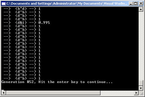
Figure 3 - Genomes of Generation 50 for the output of Bit 0
The logic for the first output bit was easily discovered after only 50 generations. As shown in Figure 3, the logic for the output of bit 0 is d ^ b (or d exclusive or'ed with b). The circuit for this output is shown below in Figure 4.
Figure 4 - Circuit for output of bit 0 of the Adder
By uncommenting the line that checks bit 1 fitness, we can run our genetic algorithm on our adder inputs against the bit 1 output. Below is the fitness function determining the error of the output calculated for the genome against the desired output of bit 1:
double
error = 100 - Math.Abs(measure[i,measure.GetLength(1) - 2] - calc); // fitness against bit 1 output
If we now run several generations on the new fitness function we see the following converged logic output on our genome population:
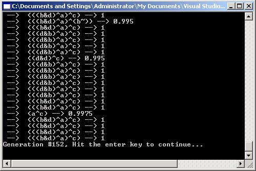
Figure 5 - Genomes of Generation 50 for the output of Bit 1
The corresponding logic circuit for this output is shown in figure 5 is shown in Figure 6 below:
Figure 6 - Circuit for output of bit 1 of the Adder
Finally we change our fitness function one more time to produce a fitness against output bit 2
double error = 100 - Math.Abs(measure[i,measure.GetLength(1) - 3] - calc); // fitness against bit 2 output