This article has been excerpted from book "Graphics Programming with GDI+".
There are many types of transformations
Translation is a transformation of the xy plane that moves a graphics object towards or away from the origin of the surface in the x- or y-direction. For example, moving an object from point A (x1, y1) to point B (x2, y2) is a translation operation in which an object is being moved (y2 - y1) points in the y-direction.
Rotation moves an object around a fixed angle around the center of the plane.
In the reflection transformation, an object moves to a position in the opposite direction from an axis, along a line perpendicular to the axis. The resulting object is the same distance from the axis as the original point, but in the opposite direction.
Simple transformations, including rotation, scaling, and reflection are called linear transformations. A linear transformation followed by translation is called an affine transformation.
The shearing transformation skews objects based on a shear factor. In the sample applications discussed throughout this article, will see how to use these transformations in GDI+.
So far we've looked at only simple transformations. Now let's discuss some more complex transformation-related functionality defined in the .NET Framework library.
What Can You Transform?
You have just seen the basics of transforming lines. We can also transform graphics objects such as points, curves, shapes images, text, colors and textures, as well as colors and images used in pens and brushes.
The Matrix Class and Transformation
Matrices play a vital role in the transformation process. A matrix is a multidimensional array of values in which each item in the array represents one value of the transformation operation, as we will see in the examples later in this article.
In GDI+, the Matrix class represents a 3X2 matrix that contains x,y, and w values in the first, second, and third columns, respectively.
Note: Before using the Matrix class in your applications, you need to add a reference to the System.Drawing.Drawing2D namespace.
We can create a Matrix object by using its overloaded constructors, which take an array of points (hold the matrix items) as arguments. The following code snipped creates three Matrix objects from different overloaded constructor. The first Matrix object has no values for its items. The second and third objects have integer and floating point values, respectively, for the first six items of the matrix.
Matrix M1 = new Matrix();
Matrix M2 = new Matrix(2, 1, 3, 1, 0, 4);
Matrix M3 = new Matrix(0.0f, 1.0f, -1.0f, 0.0f, 0.0f, 0.0f);
TABLE 10.1: Matrix properties
|
Property |
Description |
|
Elements |
Returns an array containing matrix elements. |
|
IsIdentity |
Returns true if the matrix is an identity matrix, otherwise returns false. |
|
IsInvertible |
Returns true if a matrix is invertible; otherwise returns false. |
|
OffsetX |
Returns the x translation value of a matrix. |
|
OffsetY |
Returns the y translation value of a matrix. |
The Matrix class provides properties for accessing and setting its member values. Table 10.1 describes these properties.
The Matrix class provides methods to invert, rotate, scale, and transform matrices. The Invert method is used to reverse a matrix if it is invertible. This method takes no parameters.
Note: The Transform property of the Graphics class is used to apply a transformation in the form of a Matrix object. We will discuss this property in more detail in Section 10.4.
Listing 10.6 uses the Invert method to invert a matrix. We create a Matrix object and read its original values. Then we call the Invert method and read the new values.
LISTING 10.6: Inverting a matrix
private void Form1_Paint(object sender, PaintEventArgs e)
{
string str = "Original values: ";
//Create a Matrix object
Matrix X = new Matrix(2, 1, 3, 1, 0, 4);
//Write its value
for (int i = 0; i < X.Elements.Length; i++)
{
str += X.Elements[i].ToString();
str += ", ";
}
str += "\n";
str += "Inverted values : ";
//Invert matrix
X.Invert();
float[] pts = X.Elements;
//Read inverted matrix
for (int i = 0; i < pts.Length; i++)
{
str += pts[i].ToString();
str += ", ";
}
//Display result
MessageBox.Show(str);
}
The Multiply method multiples a new matrix against an existing matrix and stores the result in the first matrix. Multiply takes two arguments. The first is the new matrix by which you want to multiply the existing matrix, and the second is an optional MatrixOrder argument that indicates the order of multiplication.
The MatrixOrder enumeration has two values: Append and Prepend. Append specifies that the new operation is applied after the preceding operation; Prepend specifies that the new operation is applied before the preceding operation during cumulative operations. Listing 10.7 multiplies two matrixes. We create two Matrix objects and use the Multiply method to multiply the second matrix by the first. Then we read and display the resultant matrix.
LISTING 10.7: Multiplying two matrices
private void Form1_Paint(object sender, PaintEventArgs e)
{
string str = null;
//Create two Matrix objects
Matrix X =
new Matrix(2.0f, 1.0f, 3.0f, 1.0f, 0.0f, 4.0f);
Matrix Y =
new Matrix(0.0f, 1.0f, -1.0f, 0.0f, 0.0f, 0.0f);
//Multiply two matrices
X.Multiply(Y, MatrixOrder.Append);
//Read the resultant matrix
for (int i = 0; i < X.Elements.Length; i++)
{
str += X.Elements[i].ToString();
str += ", ";
}
//Display result
MessageBox.Show(str);
}
The Reset method resets a matrix to the identity matrix (see Figure 10.21 for an example of an identity matrix). If we call the Reset method and then apply a matrix to transform an object, the result will be the original object.
The Rotate and RotateAt methods are used to rotate a matrix. The Rotate method rotates a matrix at a specified angle. This method takes two arguments: a floating point value specifying the angle, and (optionally) the matrix order. The RotateAt method is useful when you need to change the center of the rotation. Its first parameter is the angle; the second parameter (of type float) specifies the center of rotation. The third (optional) parameter is the matrix order.
Listing 10.8 simply creates a Graphics object using the CreateGraphics method and calls DrawLine and FillRectangle to draw a line and fill a rectangle, respectively.
LISTING 10.8: Drawing a line and filling a rectangle
private void Form1_Paint(object sender, PaintEventArgs e)
{
//Create a Graphics object
Graphics g = this.CreateGraphics();
g.Clear(this.BackColor);
//Draw a line
g.DrawLine(new Pen(Color.Green, 3),
new Point(120, 50),
new Point(200, 50));
//Fill a rectangle
g.FillRectangle(Brushes.Blue,
200, 100, 100, 60);
//Dispose of object
g.Dispose();
}
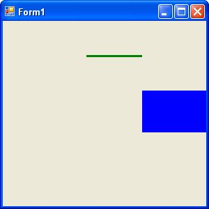
FIGURE 10.8: Drawing a line and filling a rectangle
Figure 10.8 shows the output from Listing 10.8.
Now let's rotate our graphics object, using the Matrix object. In Listing 10.9 we create a Matrix object, call its Rotate method to rotate the matrix 45 degree, and apply the Matrix object to the Graphics object by setting its Transform property.
LISTING 10.9: Rotating graphics objects
private void Form1_Paint(object sender, PaintEventArgs e)
{
//Create a Graphics object
Graphics g = this.CreateGraphics();
//Create a Matrix object
Matrix X = new Matrix();
//Rotate by 45 degrees
X.Rotate(45, MatrixOrder.Append);
//Apply Matrix object to the Graphics object
//(i.e., to all the graphics items
//draw on the Graphics object)
g.Transform = X;
//Draw a line
g.DrawLine(new Pen(Color.Green, 3),
new Point(120, 50),
new Point(200, 50));
//Fill a rectangle
g.FillRectangle(Brushes.Blue,
200, 100, 100, 60);
//Dispose of object
g.Dispose();
}
Figure 10.9 shows the next output. Both objects (line and rectangle) have been rotate 45 degrees.
New let's replace Rotate with RotateAt, as in Listing 10.10.
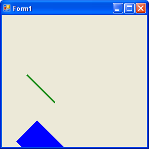
FIGURE 10.9: Rotating Graphics objects
LISTING 10.10: Using the RotateAt method
private void Form1_Paint(object sender, PaintEventArgs e)
{
//Create a Graphics object
Graphics g = this.CreateGraphics();
g.Clear(this.BackColor);
//Create a Matrix object
Matrix X = new Matrix();
//Create a point
PointF pt = new PointF(180.0f, 50.0f);
//Rotate by 45 degrees
X.RotateAt(45, pt, MatrixOrder.Append);
//Apply the matrix object to the Graphics object
//(i.e., to all the graphics items
//drawn on the Graphics object)
g.Transform = X;
//Draw a line
g.DrawLine(new Pen(Color.Green, 3),
new Point(120, 50),
new Point(200, 50));
//Fill a rectangle
g.FillRectangle(Brushes.Blue,
200, 100, 100, 60);
//Dispose of object
g.Dispose();
}
This new code generates Figure 10.10.
I we call the Reset Method is Listing 10.10 after RotateAt and before g.Transform like this:
X.RotateAt(45, pt, MatrixOrder.Append);
//Reset the matrix
X.Reset();
//Apply the Matrix object to the Graphics object
//(i.e., to all the graphics items
//drawn to the Graphics object)
g.Transform = X;
the revised code generates Figure 10.11, which is the same as Figure 10.8. There is no rotation because the Reset method resets the transformation.
The Scale method scales a matrix in the x- and y-directions. This method takes two floating values (scale factors), for the x- and y-axes, respectively. In Listing 10.11 we draw a rectangle with a width of 20 and a height of 30. Then we create a Matrix object and scale it by calling its Scale method with argument 3 and 4 in the x- and y-directions, respectively.
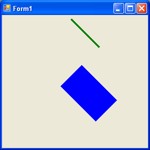
FIGURE 10.10: Using the RotateAt method
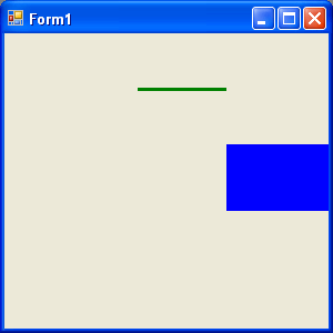
FIGURE 10.11: Resetting a transformation
LISTING 10.11: Scaling graphics objects
private void Form1_Paint(object sender, PaintEventArgs e)
{
//Create Graphics object
Graphics g = this.CreateGraphics();
g.Clear(this.BackColor);
//Draw a filled rectangle with width 20 and height 30
g.FillRectangle(Brushes.Blue, 20, 20, 20, 30);
//Create Matrix object
Matrix X = new Matrix();
//Apply 3X scaling
X.Scale(3, 4, MatrixOrder.Append);
//Apply transformation on the form
g.Transform = X;
//Draw a filled rectangle with width 20 and height 30
g.FillRectangle(Brushes.Blue, 20, 20, 20, 30);
//Dispose of object
g.Dispose();
}
Figure 10.12 shows the output from Listing 10.11. The first rectangle is the original rectangle; the second is the scaled rectangle, in which the x position (and width) is scaled by 3, and the y position (and height) is scaled by 4.
The Shear method provides a shearing transformation and takes two floating point arguments, which represent the horizontal and vertical shear factors, respectively. In Listing 10.12 we draw a filled rectangle with a hatch brush. Then we call the Shear method to shear the matrix by 2 in the vertical direction, and we use Transform to apply the Matrix object.
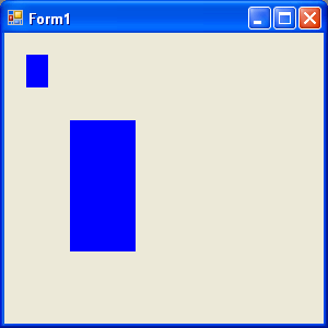
FIGURE 10.12: Scaling a rectangle
LISTING 10.12: Shearing graphics objects
private void Form1_Paint(object sender, PaintEventArgs e)
{
//Create a Graphics object
Graphics g = this.CreateGraphics();
g.Clear(this.BackColor);
//Create a brush
HatchBrush hBrush = new HatchBrush
(HatchStyle.DarkVertical,
Color.Green, Color.Yellow);
//fill a rectangle
g.FillRectangle(hBrush,
100, 50, 100, 60);
//Create a MAtrix object
Matrix X = new Matrix();
//Shear
X.Shear(2, 1);
//Apply transformation
g.Transform = X;
//Fill rectangle
g.FillRectangle(hBrush, 10, 100, 100, 60);
//Dispose of objects
hBrush.Dispose();
}
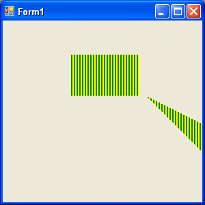
FIGURE 10.13: Shearing a rectangle
Figure 10.13 shows the output from Listing 10.12. The first rectangle in this figure is the original; the second is sheared.
The Translate method translates objects by the specified value. This method takes two floating point arguments, which represent the x and y offsets. For example, Listing 10.13 translates the original rectangle by 100 pixels each in the x- and y-directions.
LISTING 10.13: Translating graphics object
private void Form1_Paint(object sender, PaintEventArgs e)
{
//Create a Graphics object
Graphics g = this.CreateGraphics();
g.Clear(this.BackColor);
//Draw a filled rectangle
g.FillRectangle(Brushes.Blue,
50, 50, 100, 60);
//Create a Matrix object
Matrix X = new Matrix();
//Translate by 100 in the x direction
//and 100 in the y direction
X.Translate(100, 100);
//Apply transformation
g.Transform = X;
//Draw a filled rectangle after translation
g.FillRectangle(Brushes.Blue,
50, 50, 100, 60);
//Dispose of object
g.Dispose();
}
Here we draw two rectangles with a width of 100 and a height of 60. Both rectangles start at (50, 50), but the code generates Figure 10.14. Even thought the rectangle were drawn with the same size and location, the second rectangle were drawn with the same size and location, the second rectangle after translation is now located 100 point away in the x- and y-direction from the first rectangle.
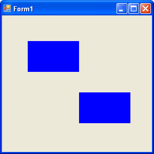
FIGURE 10.14: Translating a rectangle
Conclusion
Hope the article would have helped you in understanding Transformation Types in GDI+. Read other articles on GDI+ on the website.
|

|
This book teaches .NET developers how to work with GDI+ as they develop applications that include graphics, or that interact with monitors or printers. It begins by explaining the difference between GDI and GDI+, and covering the basic concepts of graphics programming in Windows. |